GR Yaris (Gen 2) GR Yaris GEN 2 - Heat soak issues

- I had the carbon inlet duct from Forge to direct cold outside air to the airbox intake flap. IAT logging clearly showed lower temps (does it fit mk2?)
- Get a Swedish DO88 full height IC. Catches lots more airflow and brings manifold temps right down once you drive again. (if allowed in TA)
- Consider larger hood vents to vent out hot air.
- I had a discussion with the company behind XBB to make the XBB tell the car to keep the fan on, project didn't happen due to selling my car

Actually getting temps down is better than fooling the car...
 
Venting,

Venting.webp
 
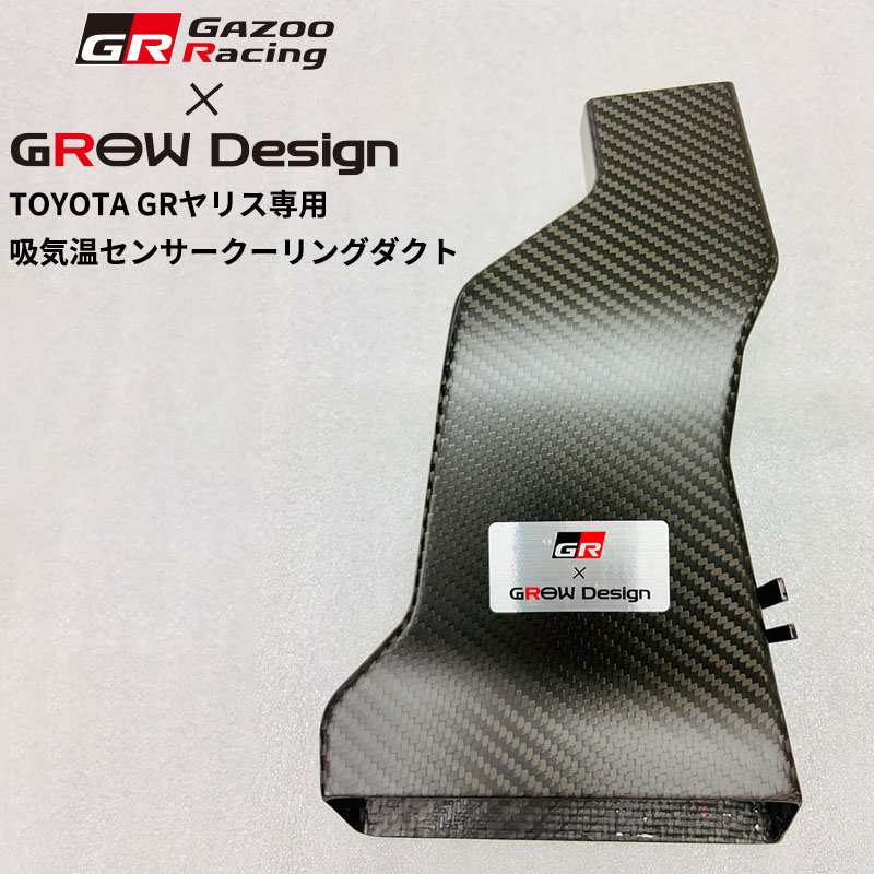
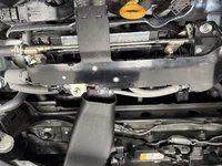
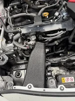
A cooling duct for the temperature sensor is being released by the shop of Mr. Sasaki, a Toyota racing driver. Of course, as everyone says, the ideal approach is to lower the overall temperature inside the engine bay—after all, Toyota cut a hole in the hood for the GR Yaris APP. which speaks for itself. However, since the ECU reduces boost pressure when the temperature in that specific area rises, it would be great to prevent that drop by simply cooling the sensor. It turns out that the temperature sensor—which is co-located with the pressure sensor on the intake manifold—gets blasted by hot air coming off the radiator. Ideally, it should be measuring the actual intake manifold temperature. The duct is designed to cool the sensor so it can function correctly. It seems the boost pressure isn't being reduced because the engine is dangerously hot, but rather because of the heat affecting that specific sensor.

I wonder if the conversion from Japanese is working properly?


Looks to be an official GR product from Grow.

Efficiently cools the intake temperature sensor and reduces power down during continuous driving
Maintain stable engine performance even on circuit driving
​

The intake temperature of the engine is checked in two places, the air cleaner part and the intake manifold part, but when you circle the circuit, etc., the hot air close to 100 degrees ° through the radiator in front of the intake temperature sensor Affected by, the temperature of the sensor itself rises.

As a result, a higher value than the air temperature actually inhaled into the intake manifold is entered into the ECU, and the ECU determines that the intake temperature is high. In order to control the direction that suppresses the engine power, the driver feels the "tar" due to power down as he drives.

The new product "Suction Temperature Sensor Cooling Duct" efficiently absorbs running wind from the bumper opening and cools near the intake temperature sensor at the intake manifold. By accurately measuring a value close to the actual intake air temperature, the original power of the engine is maintained and stable continuous driving with less "tare" is achieved.
It demonstrates stable performance even in harsh scenes such as circuit driving.
IMG_2497.webp
 
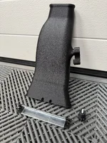
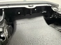
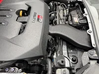
Been looking around for products that solve this. The only ones I could find were the PIRAS duct and the GROW one (Japan only?) linked above. Both look well made, but neither approaches the problem quite the way I wanted to. I don't really care about carbon fibre, I just want the problem solved.

So I scanned the area and started designing my own take on it. While I was in there I noticed there's a hot coolant pipe just behind the sensor radiating a lot of heat straight at it. Ducting cold air at the sensor helps, but you're fighting that radiation the whole time. So I went with a two-stage approach: a duct feeding air from the front, plus a heat shield blocking the radiant heat from behind.

On the Revolution resistor mod someone posted above, that just lies to the ECU. It'll work, but you also lose the protection for when intake temps really are too high. I'd rather get the actual temperature down so the sensor tells the truth.


1.webp4.webp5.webp3.webp2.webp
 
I can certainly see the side effects of excessive hot air from the fan influencing this sensor and for the need to pass cooler air over it. Do wonder though in winter conditions forcing very cold air to this same sensor what effects that might have
 
I can certainly see the side effects of excessive hot air from the fan influencing this sensor and for the need to pass cooler air over it. Do wonder though in winter conditions forcing very cold air to this same sensor what effects that might have
haven't been an issue, and have been driving in -20'C.
Have thought of skipping the TB water circuit as it feels stupid to bring any heat to the system - its kind of hard to think that it would freeze in any situations. Old cars didn' thave it and they survived.
 
I can certainly see the side effects of excessive hot air from the fan influencing this sensor and for the need to pass cooler air over it. Do wonder though in winter conditions forcing very cold air to this same sensor what effects that might have
Yeah I do not think there is a need for the extra air in the winter. The dukt is very easy to instal / remove. I will only run it in the summer times.
 
Back
Top