GR Yaris CAN Bus Reverse Engineering

tonic

Obsessed member
Aug 31, 2023
154
470
63
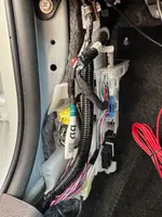
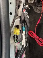
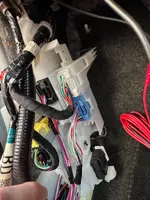
Been doing some CAN bus reverse engineering lately. All logging is done via the Network Gateway connector H62.
It's an empty plug Toyota generously left us by the RH footwell :D

CAN_connector.webp


H62.webp


Pretty happy with the results so far. My main goal was to find driver inputs (pedals, steering wheel) and interesting sensors (RPM, temps, oil pressure) for data logging. Managed to locate most of them so far, though oil pressure and temp signals are still missing. Not entirely sure if those are even available on H62.

I expect this to have some inaccuracies. I'll update the list as I progress.

CAN_PIDs.webp
 
Last edited:
Is FUEL the tank level remaining? If so that's a great find - as thought might have to use the voltage reading that goes into the back of the clocks...
 
Nice work - DM'd you some more...
Thanks, man! I'll add them to the list and tidy up my naming.
Is FUEL the tank level remaining? If so that's a great find - as thought might have to use the voltage reading that goes into the back of the clocks...
No, I believe it's the real-time fuel supply for the engine in ml. It could potentially be used for momentary or average fuel consumption on your dash.
Do you know what CAN bus, 1,2 or 3?.
According to diagram, H62 is connected to the Bus Buffer ECU (Bus 7). I'm not entirely sure what that means :) but I am definitely seeing signals from various buses, not certain if it's from all of them.
C449235C01.webp

can_desc.webp
 
Hi there,

This is super interesting - thanks for sharing all the detail.

I have an Aim Solo DL 2 which I've been trying to figure out how to properly plug into my GR Yaris in order to pick up more of these signals. With the stock OBDII connector (so far) I've only been able to pick up RPM figures but nothing more interesting (e.g. throttle, brake pressure, etc). I'm wondering if it's possible to use this separate connector to pick up the CAN-/+ signal in order to get more information?

Given this was your original intention, I wondered if you'd been able to make any progress with logging applications of the data?
 
  • Like
Reactions: S390
My goal is to use this DIY solution (https://github.com/timurrrr/RaceChronoDiyBleDevice) to feed CAN data to RaceChrono. I was successfully doing this with my previous car, Suzuki Swift Sport. It achieved a sample rate of around 50Hz, which is much faster compared to the OBDLink LX connected to the OBD-II port, which peaks at 7Hz.

I briefly tested the this solution on my GRY, and it showed similar performance. However, there were some interpretation issues with certain CAN messages, which I haven't had time to resolve.

Another option is to use the OBDLink LX connected directly to the CAN bus. I haven’t tested it yet. The OBDLink LX is more mature hardware compared to the DIY solution, which is important when connecting something to your car’s CAN bus.

I’m not sure yet which approach I’ll choose. I plan to continue this project in the spring and will share my results then.

If anyone is interested, feel free to drop me a message, and I can share my latest DBC file with you.
 
That's a very cool project.

I'm a bit of a novice but wondering if there's a way I can create my own CAN protocol for the Aim Solo using the table you've shared. My assumption is that I'd need to connect to the CAN -/+ connector on the H62 - is there a different from this connection to the one that comes over the OBDII port? Presumably you also got power and GND from somewhere else when you had it set up on your GRY? Any chance you can share a bit more detail as to how that setup looked?

Many thanks.
 
sorry to jump into a subject that - to me - has as much as fascinating as "over my head"... good work: you 'rocket-scientist!! 😁
Could I borrow your brains for the best/preferred approach to add a dashboard toggle-button to manually switch-on the radiator cooling fan?? (for those summer days/track days that we want to fight back under-bonnet heat soak)

Long gone the times where we could hardwire a button into a relay call it the day... eheh
Knowing that the fan is one of those fancy PWM-type... is there any way to tap into its circuit to "tell it" to run at (for ex.) 50% duty cycle? Or fool the fan-controller as if the AC was turn-on?
Cheers and -once again- sorry to hijack the main topic :)
 
  • Like
Reactions: Fred
sorry to jump into a subject that - to me - has as much as fascinating as "over my head"... good work: you 'rocket-scientist!! 😁
Could I borrow your brains for the best/preferred approach to add a dashboard toggle-button to manually switch-on the radiator cooling fan?? (for those summer days/track days that we want to fight back under-bonnet heat soak)

Long gone the times where we could hardwire a button into a relay call it the day... eheh
Knowing that the fan is one of those fancy PWM-type... is there any way to tap into its circuit to "tell it" to run at (for ex.) 50% duty cycle? Or fool the fan-controller as if the AC was turn-on?
Cheers and -once again- sorry to hijack the main topic :)
The GRY radiator fan has its own ECU, which receives signals from the engine ECU.

coooling_fan.webp

Toyota's diagnostic software (GTS+) includes a function to control the engine cooling fan duty ratio for testing purposes.

It should be possible to capture the data packets traveling from GTS+ to the diagnostic port, reverse-engineer the communication, and then reuse the control messages from a phone's terminal app to control the fan. This is similar to what @dvim did here: https://www.gr-yaris.co.uk/posts/142093/.

Unfortunately, I don't have a GTS+ subscription or the necessary cable to explore this further.
 
Thank you! I'm going to try creating a cable from this to a female OBDII for the Aim Solo 2DL (similar to this approach). Were you able to draw power/gnd from somewhere nearby when you ran this on your GRY?
 
  • Like
Reactions: GRandemakina
I was running this setup for reverse engineering the CAN bus, so the installation was temporary and powered via the laptop's USB. My plan for a permanent installation was to use a fuse tap to draw 12V from the internal fuse box above the driver's feet (LHD car) and to ground it using a nearby body bolt.

fuse_tap.webp
 
@tonic sorry for another novice question but do you know which pin is high/low on the H64 connector in your image? I'm trying to crimp the connectors without being in front of the car!
 
Thanks, I see that but I don't know which side on the receiving end it is (e.g. north or south in your picture). I assume the connected can only be oriented one way.
 
Hmm. Looking at this today and my wiring looks slightly different to yours (I've got a RHD car). Either that or I'm looking at it and can't see it!?
 

Attachments